PCB pull and shear test
Solution
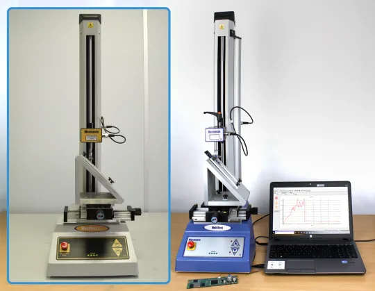
- Software-controlled force tester and software
- Adjustable X-Y table to adjust the test piece
- Custom-designed fastening jig and probes for each individual test
Benefits
- Semi-automated testing to perform both solder joint IEC tests
- One machine to meet all requirements
Requirement
A printed circuit board manufacturer wanted to perform both pull and shear tests of surface-mount solder joints according to IEC 62137-1-1 and -2 standards.
The supplier uses skilled technicians to solder very small parts by hand under a microscope, with tweezers and a fine tip soldering iron. The company wanted to undertake controlled checks to maintain quality standards, ensuring components were soldered correctly and would not break off easily when handled.
This required a special holding fixture, which could position the board at 45° and 180° to comply with the specified standards.
Solution
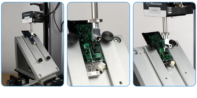
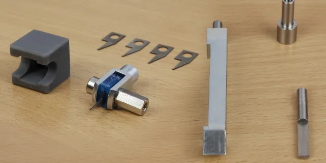
A bespoke solution was designed by Mecmesin to perform both tests. This solution included a universal tester system, 2 loadcells (50N & 500 N), a fastening jig to hold the PCB at a specified angle, and an adjustable X-Y table. Due to the miniature size of the parts to be tested, a special probe and hook were also manufactured.
The fastening jig is used for both tests as it enables the PCB to be positioned at the correct angles. The X-Y table allows fine precision alignment of the board, so that operators gain access to any component on the PCB for testing.
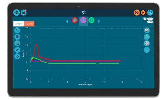
For the pull strength test, the PCB is fastened onto the jig at a 45°angle, and the sample component accurately aligned under the small test hook using the X-Y table. A 50N loadcell was employed to gain the best accuracy for low force measurements. The customer required the pull test to reach a maximum force of 20N for the connections to pass.
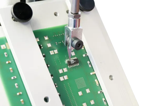
For the shear test, the PCB is positioned vertically upon the fastening jig. The special probe is lowered, effectively shearing the sample in compressive mode. A 500 N loadcell was employed for this test as the customer required the shear test to be performed up to 300 N to pass.
Test equipment
- MultiTest 1-i (replaced by OmniTest and OmniTest Touch UTMs, with VectorPro software)
- ILC 50N & 500 N loadcells (ELS loadcells for OmniTest)
- Fastening Jig - accommodates PCB's from 20x20 mm up to 100x160 mm
- Adjustable X-Y Table (for fine adjustment of PCB)
- Probe and hook to perform shear and pull tests